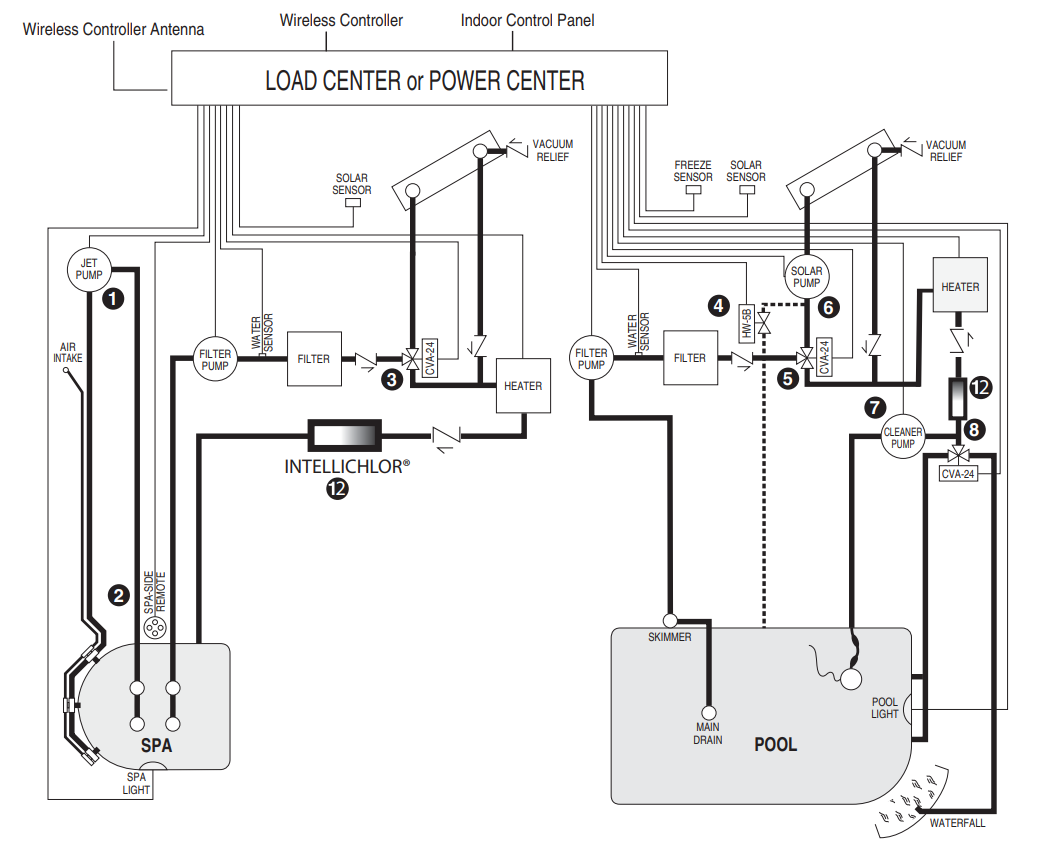
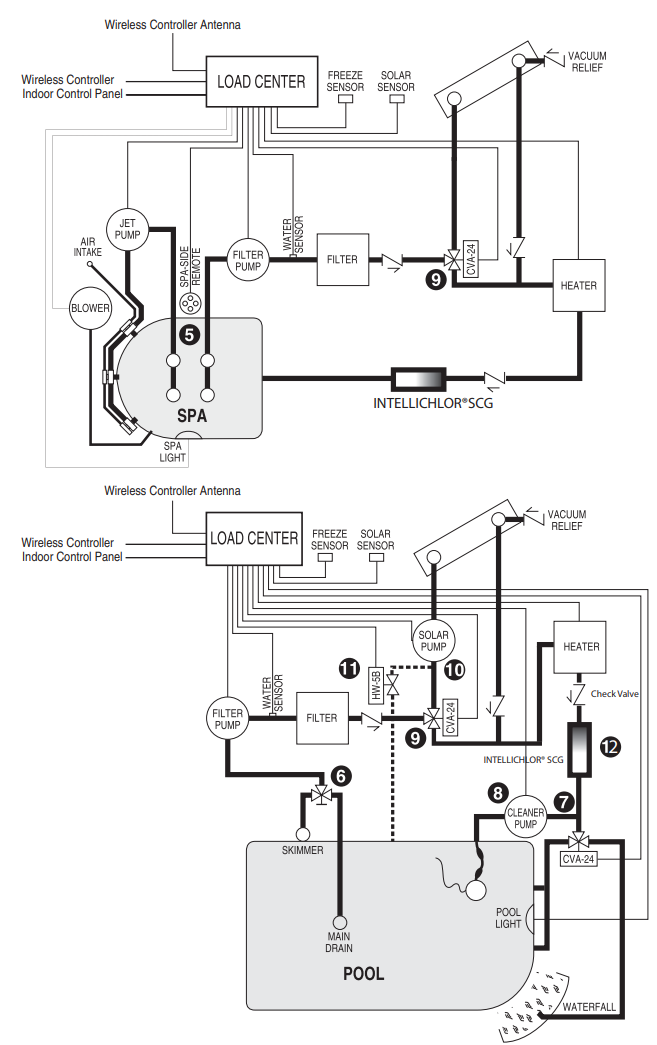
Recommended Plumbing Guidelines
- The spa should be at or above the level of the pool. If the spa is attached to the pool, provide a dam between the two bodies of water to allow the spa to overflow into the pool. If the spa is not attached to the pool, an overflow, sufficient in size to carry a full pump flow, must be installed at the water level in the spa.
- Plumb a three-port Intake Valve on the suction side of the filter pump, so that the center port of the valve is connected to the pump inlet. Connect the spa suction to one side of the Intake Valve, and the pool suction to the other side.
- Plumb a three-port Return Valve on the return side of the heater, so that the return water will enter the valve through the center port. Connect the spa return to one side of the Return Valve, and the pool return to the other side.
- If required, install a spa make-up line, consisting of a manual gate or ball valve for elevated spas and a check valve, to bypass the pool return line. This will enable some of the chemically balanced water from the pool to cycle through the spa. The manual valve will allow the amount of bypass to be adjusted.
- If the spa is to be constructed in concrete, special provisions should be made at this time for the installation of the Spa-Side remote control. Select a convenient location in the deck or above the water level in the spa wall, where the Spa-Side remote will not be submerged by the spa water, and install a 6 in. to 12 in. length of one inch PVC pipe to provide a receptacle for the Spa-Side remote. The pipe should be level and protrude beyond the finished surface of the spa. It will be cut back at a later installation time. Reduce the pipe size down to 1/2 in. or 3/4 in. conduit, and run it to the proposed Load/Power Center located at the equipment pad. Use sweep elbows for turns.
The Spa-Side remote will not be installed until the spa construction is completed. - For systems that incorporate a skimmer, it is possible to balance the amount of suction between the skimmer and the main drain for maintenance purposes. This is easily accomplished by installing a manual three-port mixing valve at the suction line. Plumb one port to the skimmer and the other to the main drain.
- If a “non-booster pump” pressure-side pool cleaner is being used, plumb a manual three-port valve between the filter pump and filter, with the third port plumbed to the pool cleaner line, and install a motorized two-port Pool Cleaner Valve at this line. The motorized valve will automatically open whenever the Control System activates the pool cleaner.
- If a booster pump pool cleaner is being used, plumb the booster pump so that its suction side is connected to the pool return after the heater and as close to the ground as practical.
- Plumb the solar feed and return lines between the filter and the heater. Install a three-port valve at the feed line. Use a Compool solar valve, model SOL-2T, to allow automatic draining of the panels.
- A solar booster pump should be used when the distance to the panels exceeds 200 ft., or the panels are elevated higher than 25 ft.
- Glazed solar panels require a drain valve, model HW-5B, to allow draining of the panels. This prevents damage from overheating water. Install a drain valve at the solar feed line and connect to the pool fill line.
Equipment Location
All equipment, with the exception of the Spa-Side remote, must be located at least 10 ft. from the water’s edge.
Hydraulic Schematic Diagrams
Recommended Hydraulic Schematic for Shared Equipment System 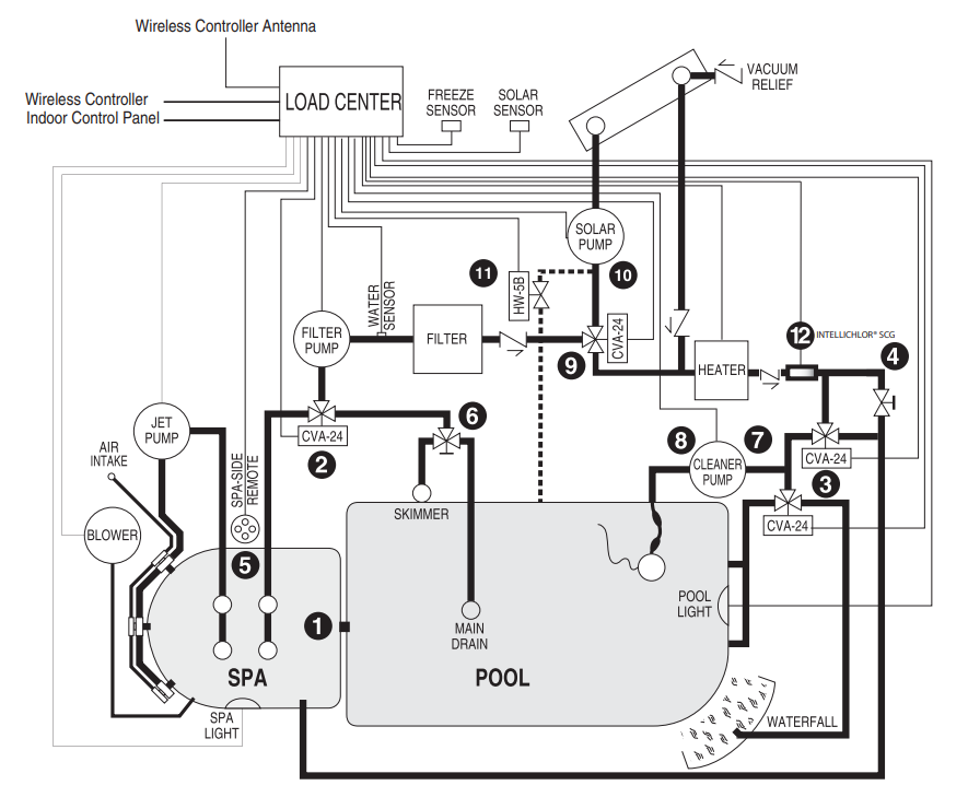
Recommended Hydraulic Schematic for Dual Equipment System
Recommended Hydraulic Schematic for Single Equipment System
Pentair IntelliTouch Control System PDF
For more details, view the Pentair Intellitouch Control System PDF.
Need More Help?
Didn't find the answer you were looking for? You can always contact us at support@royalswimmingpools.com or choose the category below to see our most frequently asked questions for that topic: